Beiträge

Function of ETCS

The function of ETCS, unifies all train control system on the European rail network. It replaces conventional country-specific train control systems, but it offers more than that. It is upward and downward compatible, in other words, an ETCS-equipped train can accept and process signals from several train protection systems.

Above all, the different levels, i.e. different technical states, shape the railroad world to an enormous extent. Incidentally, the mode of operation of the respective levels varies widely. The entire range of railroad technology is represented, from driving on sight to driving at a braking distance. The function of ETCS is therefore the central train control technology in Europe and overseas. All the relevant processes are considered in this explanatory video.

Function of a tram switch

A classic tram switch which can be set remotely is called a “single switch”. The necessary impulse for control comes from the vehicle. It is therefore not set via interlockings, as is the case with railroads. However, the technical effort and the safeguarding before, during and after the operation of such a switch is similar to the processes of a route. In this chapter, the processes of this switch system in tram operation are described chronologically.

A variant of the train-operated setting process is the methodical request by radio. With this method, the vehicle receives an order via a trackside beacon to send a radio telegram to the switch after a certain distance of track has been covered. The switch controller then gives the setting command to the switch, whereupon it sets and locks. It is then driven over and cleared, similar to a route in railroad engineering.

Definition of tram

The tram is a transport system that cannot easily be squeezed into a concrete scheme. It takes on the most diverse forms and modes of operation in the cities across the world. In this chapter, we will discuss all relevant forms of operation, both in front of and behind the scenes. In addition to the classic one-way tram, there’s also bi-directional operation. Or the tram independent of road traffic. More inconspicuous to the passenger are other forms of development, such as operation with signaling systems, depot control systems, or speed monitoring systems.

Thought one stage ahead, the tram system can occasionally be conceptualized as a train configuration coupled to each other.And last but not least, there are trams that do not even touch road traffic in any way. Especially with the last-mentioned developments, they are already initial stages or already converted systems of a light rail or subway, for which separate definitions apply in each case.

Operating points

The infrastructure of railroad systems can be clearly divided into different facilities, categorically and spatially. For this purpose, there are the so-called operating points and their respective designations. These would be, for example, junctions, transfer points, stations, stops, connection points and many more. Each of these types of operating points fulfil their own function in the overall rail operation process, which is explained in detail in our video chapter. By clearly classifying and assigning an operating point to the categories, the related operating rules and responsibilities are then defined. They standardize the behavior of driving personnel, control center personnel, but also, for example, the behavior of planning engineers.

Another part of this short video is the superordinate division of rail lines into station areas and areas of free track. It also serves to standardize procedures by establishing rules. Further, it represents a further level of categorization in rail operations. It may happen that the above-mentioned types of operating stations can be operating stations of the free track. Otherwise, it can be an operating stations of the station area.

Train configuration

Trains have a certain train configuration. This refers to how individual train sections can be combined to form an entire train set. Locomotive-hauled trains are a classic example of this, but not only in freight traffic. They also used in passenger traffic. However, they are increasingly being replaced by multiple units. These are closed vehicle units that can only be separated for workshop purposes, but no longer for operational reasons.

How the car bodies and their axles are arranged, or where the traction motor is installed, these are all criteria for the classification of trains. But there are more than the before mentioned. Each train configuration has its advantages and disadvantages. Usually, they are system decisions adapted to the environment that we deal with in this chapter.

Configuration of a safe route

The configuration of a safe route is a necessary measure before a train can safely run the planned track section. This special configuration of a safe route is segmented into six sub steps. These are also part of their respective security levels, which are required for each configuration. Only on passing each of the relevant requirements, a safe and collision-free train run is ensured.

The relevant part of railway safety is embedded in the configuration of a safe route. After initializing this route configuration, which is also called route trigger. The setting of switch positions and other movable track units begins.If these units are in correct position, the signaling control locks these track units and their positions. Subsequently the route is set, which is an intermediate safety step.Afterwards, each track sections occupation status is examined. If all track sections are free, the appropriate route signal is settable and “go” signal aspect can be shown.

Axle count system

An axle count system is a wide spread detection system in railway technology. They detect both the front and end of the train by counting and registering the axles of trains. An axle count system is composed at a minimum by two trackside axle detection units and an electronic control system. Thereby the trackside units provide the control system with input data.

At first a trackside detection unit at the beginning of a track section counts the passing wheels of a train. Thereafter another axle detection unit at the end of the same track section registers the same number of wheels passing by this train. The electronic control system processes the information of both trackside units. With the given information it can deduce, if the train occupies the track section or not. In some situation the technology fails, for example when one, of the twelve axles, is not registered entering the section. When this is the case there are special safety rules, which allow the track section to go to the status of not assigned or free. In some situations, the signal box operator or dispatcher can reset the axle count system to its basic position.

End-of-train detectors

End-of-train detectors belong to necessary basic technology of train protection. This installation recognizes the beginning and the end of trains crossing. Therefore, this is a system of point by point detection of trains. On the one hand these detectors enable that several trains can run safely on the same track. Furthermore, these detectors fulfil other important functions which we will explain in this chapter as well.

End-of-train detectors are the limit of a track section. If a train passes this detector by its head, then the following track section becomes “occupied”. When the following track section is likewise the beginning of the next block, then the signal gets the signal aspect “halt”. If the end of train finally passes the detector, then the last track section gets the status “not assigned”.   

Flank protection switch

Flank protection is one of the most important safety conditions which is realized by train routes controlled by signal boxes. As the name implies, a flank protection switch avoid collisions of trains to each other from the side. This dismissive position of the switch is normally for safe routes. For all neighbouring switches the dismissive position is a basic requirement of a route.

But not always this requirement can be implemented in logical route requirement. There are some exceptions. If there are two routes for example. When both of them need the dismissive but different position of the same flank protection switch. If switches can´t ensure flank protection, then the function has to ensured by a signal or a trackside derailer. Both the rule and the exception are explained in this clip.

Main signal and presignal

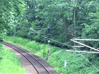
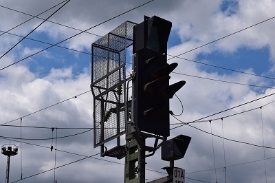
The main signal and the appropriate presignal characterize the setting of railway. But both of them do not have good prospects, because more and more cab signals substitute the trackside signals, so that these get obsolete. Nevertheless, the appreciation for the alternative signal system for railway is relevant for future. Main signals reveal state of the following block.

In other words, they predicate if the referred block is occupied, reserved or in its basic state. The presignal is an additional support in case of middle and high trackside velocities or in case of restricted of view distance. They enable a timely information about the state of the referred block by reproducing the same content as the main signal.